my first hardware challenge: blinky
In May, MakeRiga organized a great hacking event. I provided a few software challenges for the competitors while others contributed with hardware challenges. These last few days I spent some time discovering the later as I have close to no experience in hardware. Here's my journey with my first hardware challenge: Blinky. Blinky is simple circuit with a blinking red led and a green led that stays switched off.
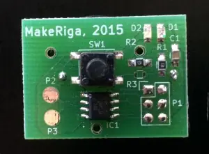
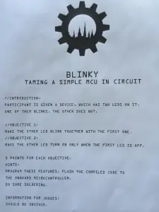
There are 2 objectives for this challenge:
-
Make the green led blick synchronously with the red led
-
Make the green led blick asynchronously with the red led
The first thing I did is look at the components on the circuit and the associated wiring.
- a chip labeled ATMEL1412 TINY13A SSU
- 1 green led, 1 red led
- 2 resistors
- 1 capacitor
- 1 switch
- 3V CR2032 battery
Of course the most interesting part is the chip and as I didn't know what it does, I searched for it on duckduckgo.com (I started google detox a few days ago and so far I'm very happy with the results Duck Duck Go gives me). Here's the official documentation for the chip.
The Atmel picoPower 8-bit AVR RISC-based microcontroller featuring 1KB of ISP Flash, 64-byte EEPROM, 64-byte SRAM, 32-Byte register file, and 4-channel 10-bit A/D converter. The device achieves up to 20 MIPS throughput at 20 MHz at 1.8-5.5 V operation.
So since it's a micro-controller, it means that there's software written inside it to blink the led. So at this stage, there are 2 ways to complete the objectives:
- hardware: solder new wires to the circuit
- software: modify the software on the chip
As I'm more of the software guy I took this approach. It ended up being much longer than the hardware approach but I really learnt a lot from it. So my first question was: how can I extract the software from the micro-controller?
I found out that you need both software and hardware for that task. For software avrdude is very popular and for hardware I opted for a USBasp programmer as we have 2 of them at MakeRiga.
Here's how it works: Avrdude communicates with the micro-controller through the USBasp. For it to work the USBasp pins must simply be connected to the corresponding pins on the ATtiny 13A micro-controller. I also had to solder pins to the circuit for easier connection.
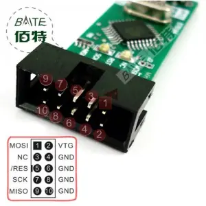
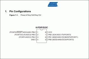
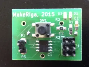
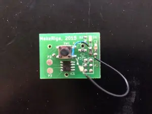
Here's how it looks with everything connected. Note that the led is blinking because the circuit is powered through the USBasp.
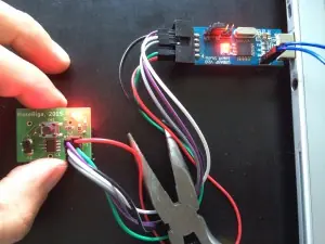
Now it's time to dump the software from the chip: avrdude -p t13 -c usbasp -U flash:r:flash-13.bin:r
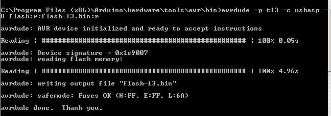
For it to work make sure that avrdude finds its config file and that the jumper 3 on USBasp is connected.
Here's a copy of flash-13.bin (it's only 64 bytes of code). To check that everything is working, let's upload the firmware back to the device. avrdude -p t13 -c usbasp -U flash:w:flash-13.bin
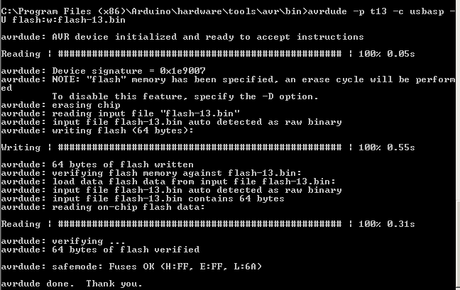
Now that we know it's working comes the next question: how can I write software for the micro-controller? I found out that the main options are Arduino IDE with a few changes or use Atmel Studio. I opted for Arduino IDE as it was a lighter download. Atmel Tiny micro-controllers are unfortunately not supported out of the box and I had to fiddle for a while until I found out how to do it thanks to this blog. In Arduino IDE, under Tools, select board ATtiny, processor ATtiny13 and clock 1Mhz internal. Next problem was to get some start source code to play with. Arduino IDE has a blink example so I started with this one.
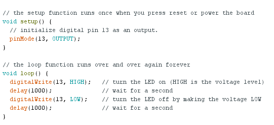
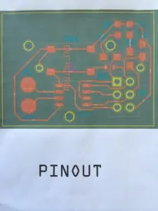
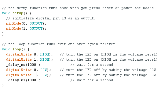
The code only required a few modifications to work. First our micro-controller only has 8 pins, so it can't be pin 13. After looking at the circuit pinout again, I concluded that PB0 is connected to the red led and PB1 to the green led and PB0 is pin 0, PB1 is pin 1. I uploaded the code and ended up with a red led but not blinking. strange... Changing the pin to 1 turned the green led and setting the digitalWrite to low would turn the light off. So I understood there was some problem with the delay function. I found out that I had to use another function named _delay_ms and that did the trick.
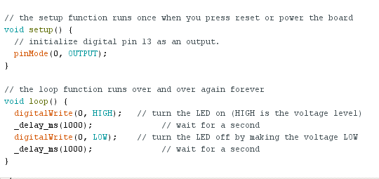
Interestingly my software ended up costing 364 bytes, which is a huge inflation compared to the original 64 bytes. Solving the objectives 1 and 2 was a piece of cake from there on. Here's the code for both leds blinking at the same time.
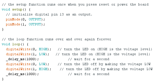
And asynchronously...
Finally the software way was much harder but definitely a lot more fun :D Here's how the hardware approach looks for the alternative blinking.
