Skip to content

3

Surveillance cameras are big business and way too expensive when you want to buy one from a reputable brand. Here's an example: Logitech Alert 750e Outdoor Master Security Camera System with Night Vision currently sells at US$999.

In this post I'll show you how to build your own surveillance camera for fun and for way cheaper. Let's get started.

For this, you'll need:
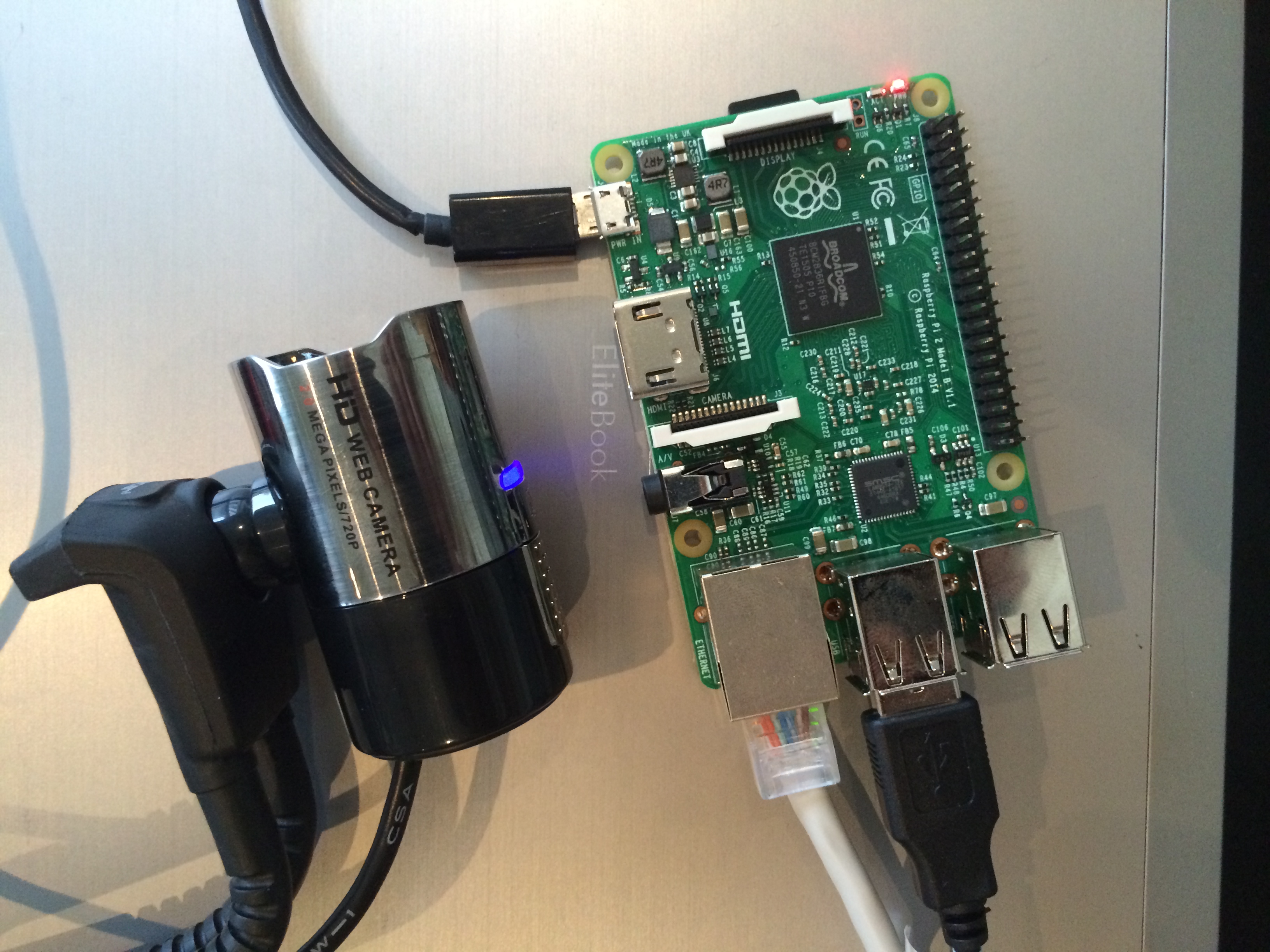
  1. a Raspberry Pi 2
  2. a 16GB micro SD card for the Raspberry software
  3. your favorite USB webcam
  4. an Ethernet cable and a router with at least one RJ-45 free LAN slot
  5. And of course a computer with an SD card reader

raspberry-pi-setupsd-card

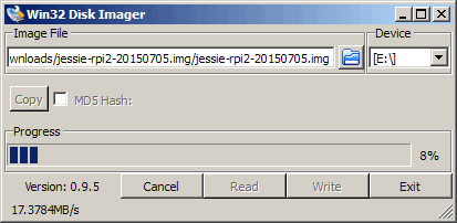
  • The first step is to download and install the operating system for the Raspberry Pi. While Raspbian the official Linux OS for the Raspberry Pi is an option, I didn't like it that much as there are way too many things that get automatically installed on it. I decided to go the leanway by installing Debian Jessie instead. Download it from here https://sjoerd.luon.net/posts/2015/02/debian-jessie-on-rpi2/ (latest image at https://images.collabora.co.uk/rpi2/jessie-rpi2-20150705.img.gz) then extract the gzip archive and use Win32DiskImager to write the downloaded image to the SD card.win32-disk-imager
  • Eject the SD card and insert it into the Raspberry Pi, then power the Raspberry using the micro-USB slot. Also connect the Raspberry to your router using Ethernet cable.
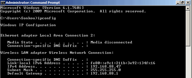
  • The Raspberry Pi will automatically boot on the SD card pre-installed image, establish an network connection and the SSH deamon will be listening for us. But first we need to find its IP address. For that we can use nmap which is a network scanner. Download and install nmap then open a command prompt .
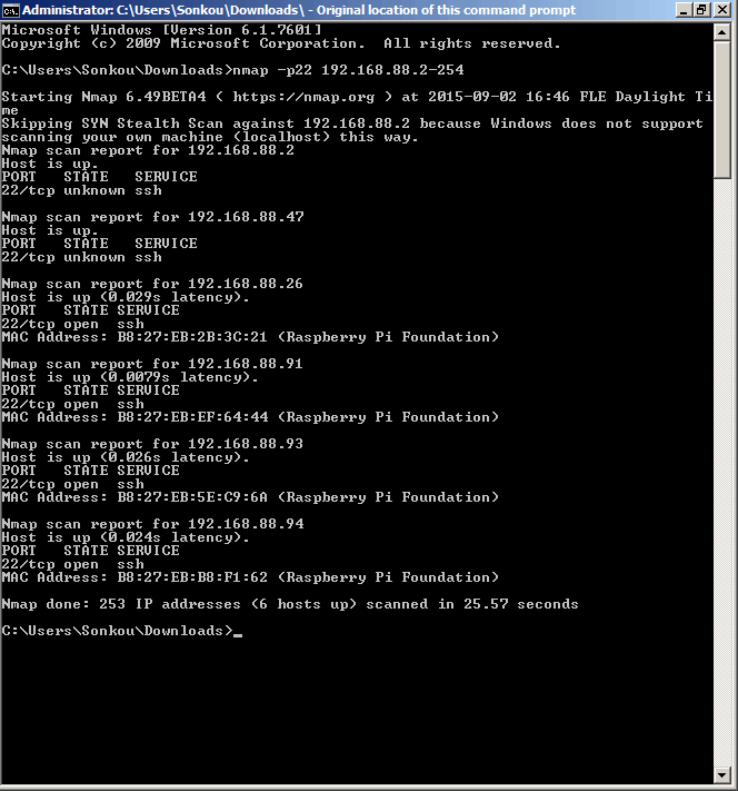
  • In the command prompt type ipconfig. This will provide valuable info about our local network. As you can see, my IP address is 192.168.88.47.ipconfig-result
  • Now we scan the network using nmap -p22 192.168.88.2-192.168.88.254 (replace 88 with your local flavor). What this does is to scan the whole local network (except for the gateway) for devices listening on port 22 which is the SSH default port.nmap-results
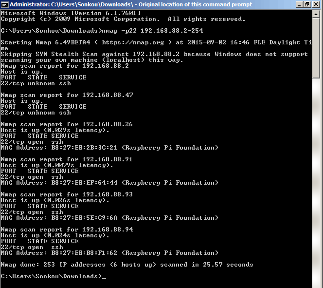
  • In this example, you can see that 6 devices are present (my computer included) and among them are 4 Raspberry Pi. Now that we have its IP address we can establish a connection using SSH. Probably the best SSH option on Windows is Putty. Download and install it.
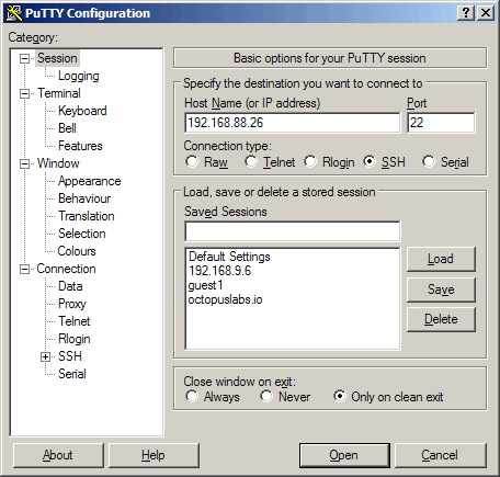
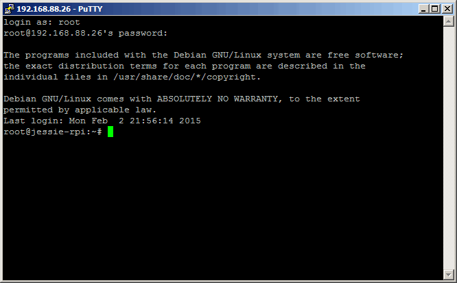
  • Start Putty and enter the IP address of the Raspberry Pi under Host name then click openputty-connect
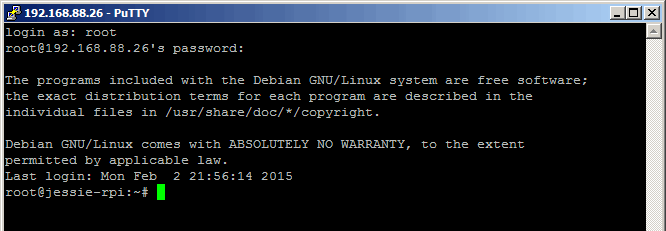
  • The default login is root/debianlogin-as-root
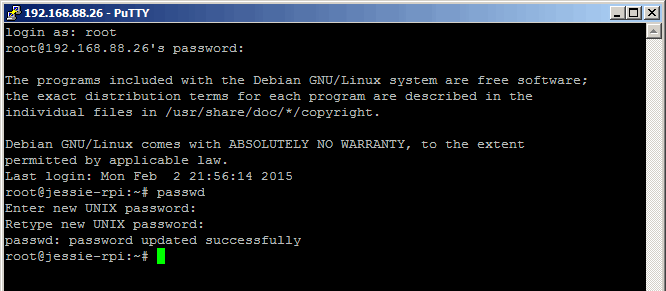
  • Start by changing the root password using the passwd commandpasswd
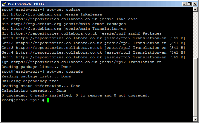
  • Update the system: apt-get update then apt-get upgradeapt-get-update
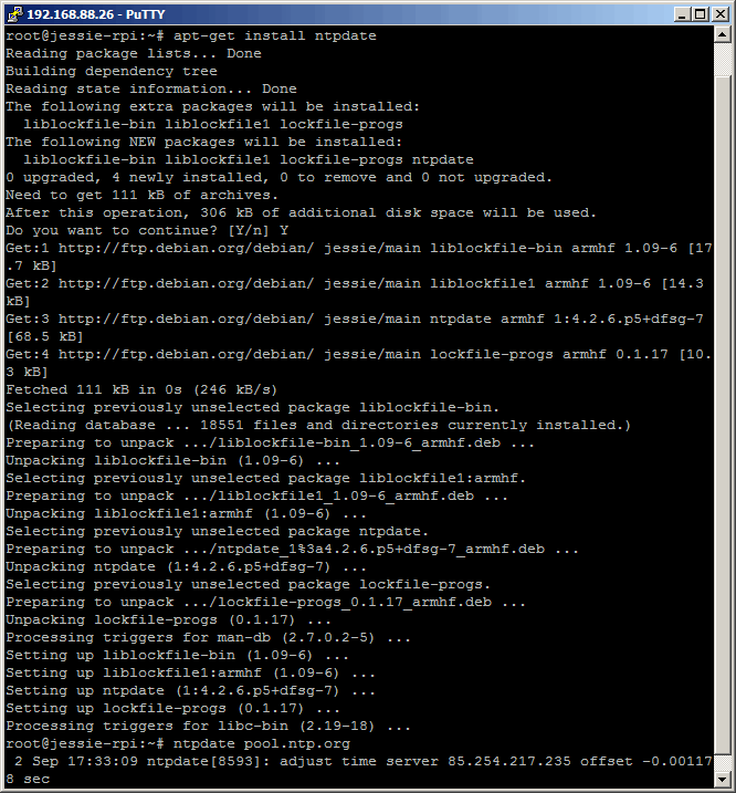
  • Update the Raspberry date, time and timezone.
    1. apt-get install ntpdate
    2. ntpdate pool.ntp.orgntpdate
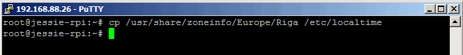
    3. cp /usr/share/zoneinfo/Europe/Riga /etc/localtime to set the time zone (adjust to your flavor)set-timezone
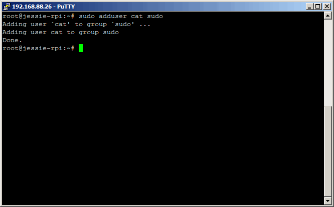
  • Install sudo and add a user account: apt-get install sudo then adduser yourusersudo-adduser
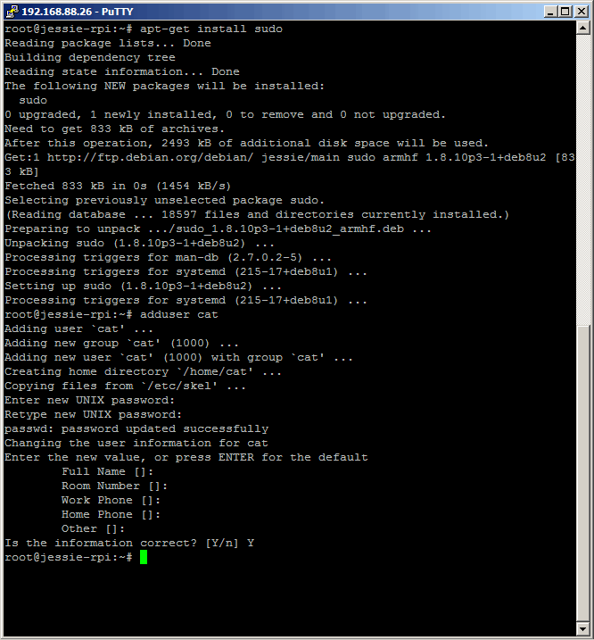
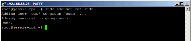
  • Make the new user a system administrator: sudo adduser cat sudosudo-adduser-2
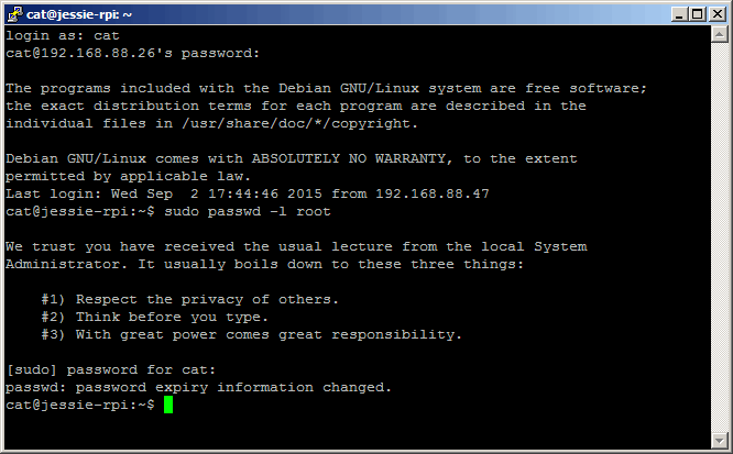
  • Now that we created the user account, let's disconnect from this session and reconnect but with the user account this time. Now let's remove the possibility to login as root. sudo passwd -l rootremove-root-loginIf you want to learn more about why it's important to disable root login...
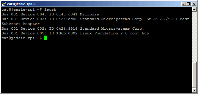
  • Add USB utilities: sudo apt-get install usbutils
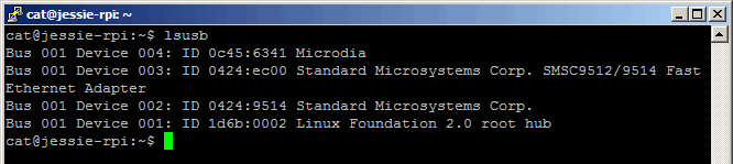
  • Check that your camera is detected: lsusb detect-usb-camera
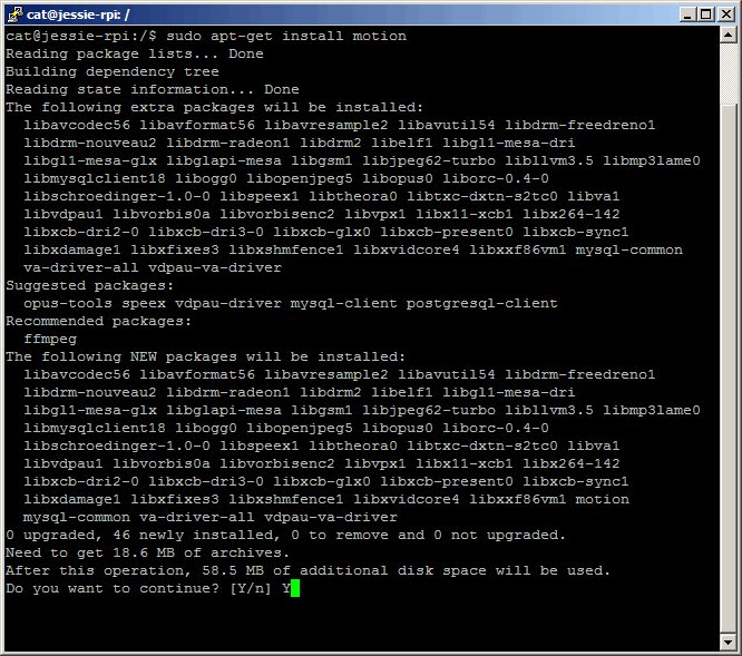
  • Install the camera software: sudo apt-get install motioninstall-motion
  • Backup the motion configuration file: sudo cp /etc/motion/motion.conf /etc/motion/motion.conf.bak
  • Edit the motion configuration file: sudo nano /etc/motion/motion.conf
  • Here's the list of changes I made on mine
    logfile /var/motion/motion.log
    width 1280
    height 960framerate 5quality 95

    #sdl_threadnr 0

    snapshot_interval 360

    target_dir /var/motion

    snapshot_filename snapshot-%Y-%m-%d_%H%M%S-%v
    picture_filename motion-%Y-%m-%d_%H%M%S-%v-%q-%v
    movie_filename movie-%Y-%m-%d_%H%M%S-%v
    timelapse_filename timelapse-%Y-%m-%d
    stream_quality 95
    stream_motion on
    stream_localhost off

Save the file CTRL + O and exit nano CTRL + X

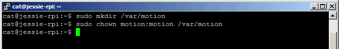
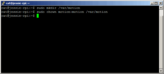
  • Create dir /var/motion/ : sudo mkdir /var/motion and assign ownership to motion: sudo chown motion:motion /var/motionmotion-dir
  • Start the motion deamon when the system starts: sudo nano /etc/default/motion and set daemon to yes
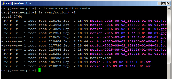
  • Test if everything works accordingly: sudo service motion restart
  • After a few seconds check if any content was generated in the motion target dir: ls /var/motion/ -lmotion-test
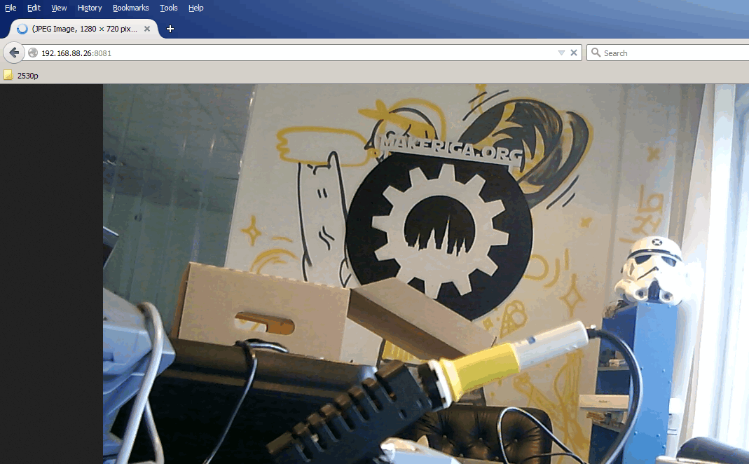
  • And even better, you can now also access the live stream server at https://192.168.88.26:8081 . Well that's it! If you have any issues or problems, just report them in the comments section.live-stream
  • Update: if you notice after reboot that no photos are being captured, here's how to troubleshoot: sudo service motion status. This will show the status of the motion service and will show any errors that could have occurred. It's usually permission issues on the motion config file or the motion log file which can be fixed with chown and chmod.

I recently broke my iPhone 5S screen and decided that I should try to fix it myself.

I headed to ifixit.com to see how hard this could be. After a quick search on their website, I found the exact guide I needed as well as the price for a replacement screen. A quick look at the repair guide convinced me and off I went to order the replacement screen. A week later or so I received the package and was ready to start the surgery 🙂

Following the guide made the repair relatively easy, the only issue I experienced was that the screen connector was not exactly in place the first time I tried which resulted in screen artifacts.

photo 1photo 2

photo 3photo 4


I have experienced problems with one of the 2 USBasp programmers we have at MakeRiga and decided to flash the firmware. Here's how to do it.

  • Download the latest firmware from https://www.fischl.de/usbasp/. At the time of writing this it was https://www.fischl.de/usbasp/usbasp.2011-05-28.tar.gz
  • Extract the archive
  • There are 3 firmwares inside the usbasp.2011-05-28\bin\firmware directory: usbasp.atmega88.2011-05-28.hex, usbasp.atmega8.2011-05-28.hex and usbasp.atmega48.2009-02-28.hex. The difference between them is the target micro-controller. Check which one you have.

usbasp-view-top

  • To update the firmware you also need to set jumper J2 on the USBasp to update as explained in  the Readme.txt
  • Set both USBasp to 5V on jumper J1 and connect them via a 10 pin cable
  • Finally connect the programmer to the computer USB port

usbasp-connected-to-usbasp

    • Now let's get to avrdude. Copy the correct firmware to the avrdude directory.
    • Backup the original firmware. You'll need to replace VARIABLE with your micro-controller version: atmega8, atmega48 or atmega88

avrdude -c usbasp -p VARIABLE -U flash:r:flash-usbasp.bin:r

avrdude-flash-dump-usbasp

  • To write the latest firmware. Replace FIRMWARE with your firmware

avrdude -c usbasp -p VARIABLE -U flash:w:FIRMWARE

avrdude-update-usbasp-firmware

That's it!

In May, MakeRiga organized a great hacking event. I provided a few software challenges for the competitors while others contributed with hardware challenges. These last few days I spent some time discovering the later as I have close to no experience in hardware. Here's my journey with my first hardware challenge: Blinky. Blinky is simple circuit with a blinking red led and a green led that stays switched off.

circuit


There are 2 objectives for this challenge:

  1. Make the green led blick synchronously with the red led
  2. Make the green led blick asynchronously with the red led

challenge

The first thing I did is look at the components on the circuit and the associated wiring.

circuit-pinout

  • a chip labeled ATMEL1412 TINY13A SSU
  • 1 green led, 1 red led
  • 2 resistors
  • 1 capacitor
  • 1 switch
  • 3V CR2032 battery

Of course the most interesting part is the chip and as I didn't know what it does, I searched for it on duckduckgo.com (I started google detox a few days ago and so far I'm very happy with the results Duck Duck Go gives me). Here's the official documentation for the chip.

The Atmel picoPower 8-bit AVR RISC-based microcontroller featuring 1KB of ISP Flash, 64-byte EEPROM, 64-byte SRAM, 32-Byte register file, and 4-channel 10-bit A/D converter. The device achieves up to 20 MIPS throughput at 20 MHz at 1.8-5.5 V operation.

So since it's a micro-controller, it means that there's software written inside it to blink the led. So at this stage, there are 2 ways to complete the objectives:

  • hardware: solder new wires to the circuit
  • software: modify the software on the chip

As I'm more of the software guy I took this approach. It ended up being much longer than the hardware approach but I really learnt a lot from it. So my first question was: how can I extract the software from the micro-controller?

I found out that you need both software and hardware for that task. For software avrdude is very popular and for hardware I opted for a USBasp programmer as we have 2 of them at MakeRiga. Here's how it works: Avrdude communicates with the micro-controller through the USBasp. For it to work the USBasp pins must simply be connected to the corresponding pins on the ATtiny 13A micro-controller. I also had to solder pins to the circuit for easier connection.

usbasp-pinoutattiny13-pinoutcircuit-soldered-pins

Here's how it looks with everything connected. Note that the led is blinking because the circuit is powered through the USBasp.

usbasp connected to circuit

Now it's time to dump the software from the chip:

avrdude -p t13 -c usbasp -U flash:r:flash-13.bin:r

avrdude-flash-dump

For it to work make sure that avrdude finds its config file and that the jumper 3 on USBasp is connected. Here's a copy of flash-13.bin (it's only 64 bytes of code). To check that everything is working, let's upload the firmware back to the device.

avrdude -p t13 -c usbasp -U flash:w:flash-13.bin

avrdude-flash-upload

Now that we know it's working comes the next question: how can I write software for the micro-controller? I found out that the main options are Arduino IDE with a few changes or use Atmel Studio. I opted for Arduino IDE as it was a lighter download. Atmel Tiny micro-controllers are unfortunately not supported out of the box and I had to fiddle for a while until I found out how to do it thanks to this blog.

In Arduino IDE, under Tools, select board ATtiny, processor ATtiny13 and clock 1Mhz internal.

Next problem was to get some start source code to play with. Arduino IDE has a blink example so I started with this one.

arduino-blink-example

The code only required a few modifications to work. First our micro-controller only has 8 pins, so it can't be pin 13. After looking at the circuit pinout again, I concluded that PB0 is connected to the red led and PB1 to the green led and PB0 is pin 0, PB1 is pin 1. I uploaded the code and ended up with a red led but not blinking. strange...

Changing the pin to 1 turned the green led and setting the digitalWrite to low would turn the light off. So I understood there was some problem with the delay function. I found out that I had to use another function named _delay_ms and that did the trick.

arduino-blink-example-fixed

Interestingly my software ended up costing 364 bytes, which is a huge inflation compared to the original 64 bytes.

Solving the objectives 1 and 2 was a piece of cake from there on. Here's the code for both leds blinking at the same time.

arduino-both-leds-blinking

And asynchronously...

arduino-both-leds-blinking2

Finally the software way was much harder but definitely a lot more fun 😀

Here's how the hardware approach looks for the alternative blinking.

hardware-solution